Or “How to build a portable self-powered, self-licking ice cream cone.” 😀
Several years ago, I started building what I referred to affectionately as a self-licking ice cream cone: a Renewable Energy (RE) system that powered the same IoT system that monitored it. I’ve given several talks about this system, both its hardware and its software stack, and there are so many useful (and scalable) lessons I’ve learned that I really enjoy sharing. Still learning those lessons too, btw.
Recently, Stephen Chin asked me if I could put together a portable RE IoT system to demo in the MakerZone at JavaOne this year. If a picture is worth a thousand words, a fully-built and on-premises demo must be worth at least a million, right? The idea intrigued me. Could I create a 100% fully-capable representation of a (my) real working system that would be small enough to transport to conferences and meaningful for attendees to see? Yes…yes, I thought I could. 🙂
It has been a lot of work fun!
There is much to tell, but we’ll stick to the high points for this post. More to follow.
Hardware List and Related Observations
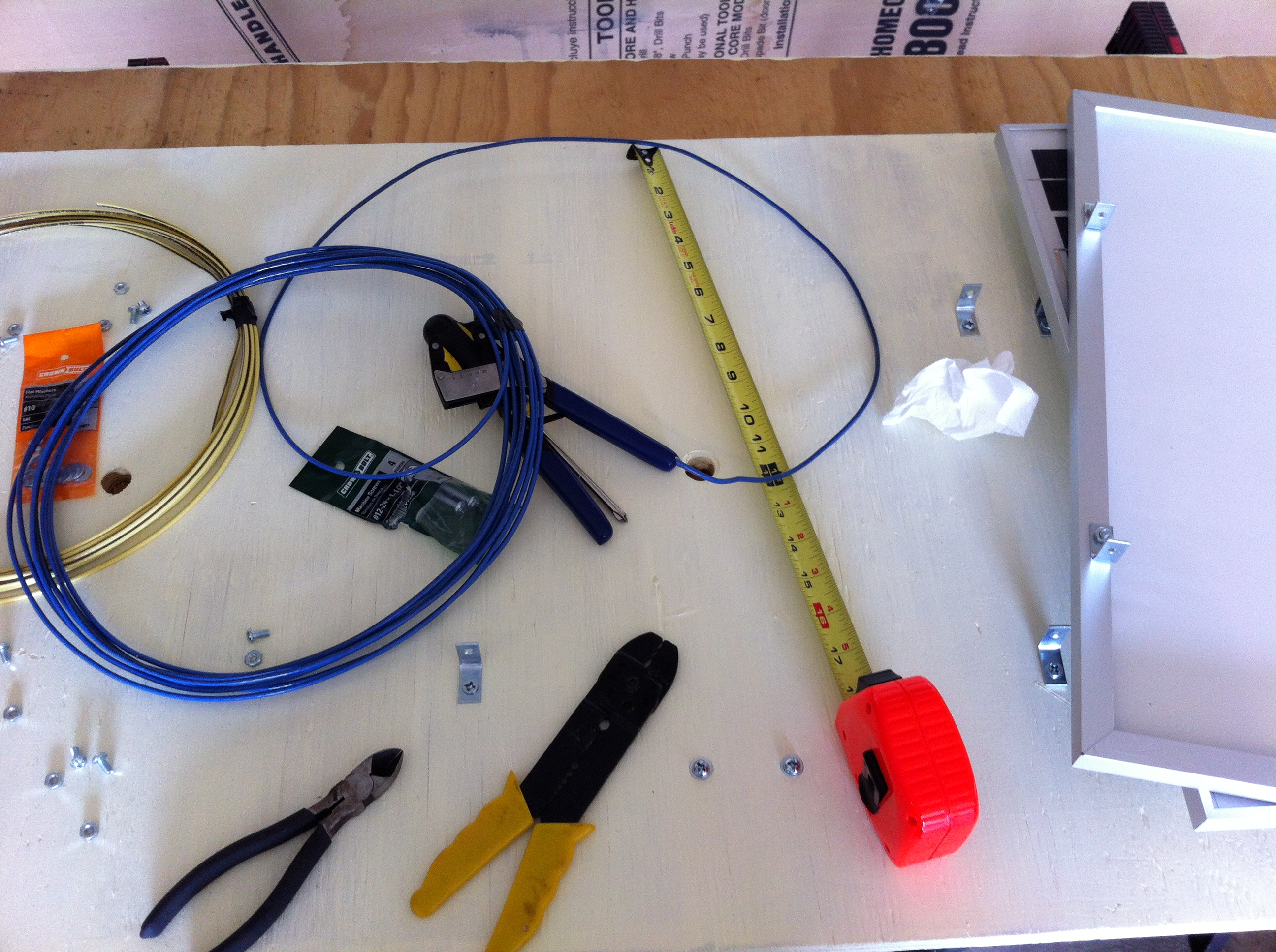
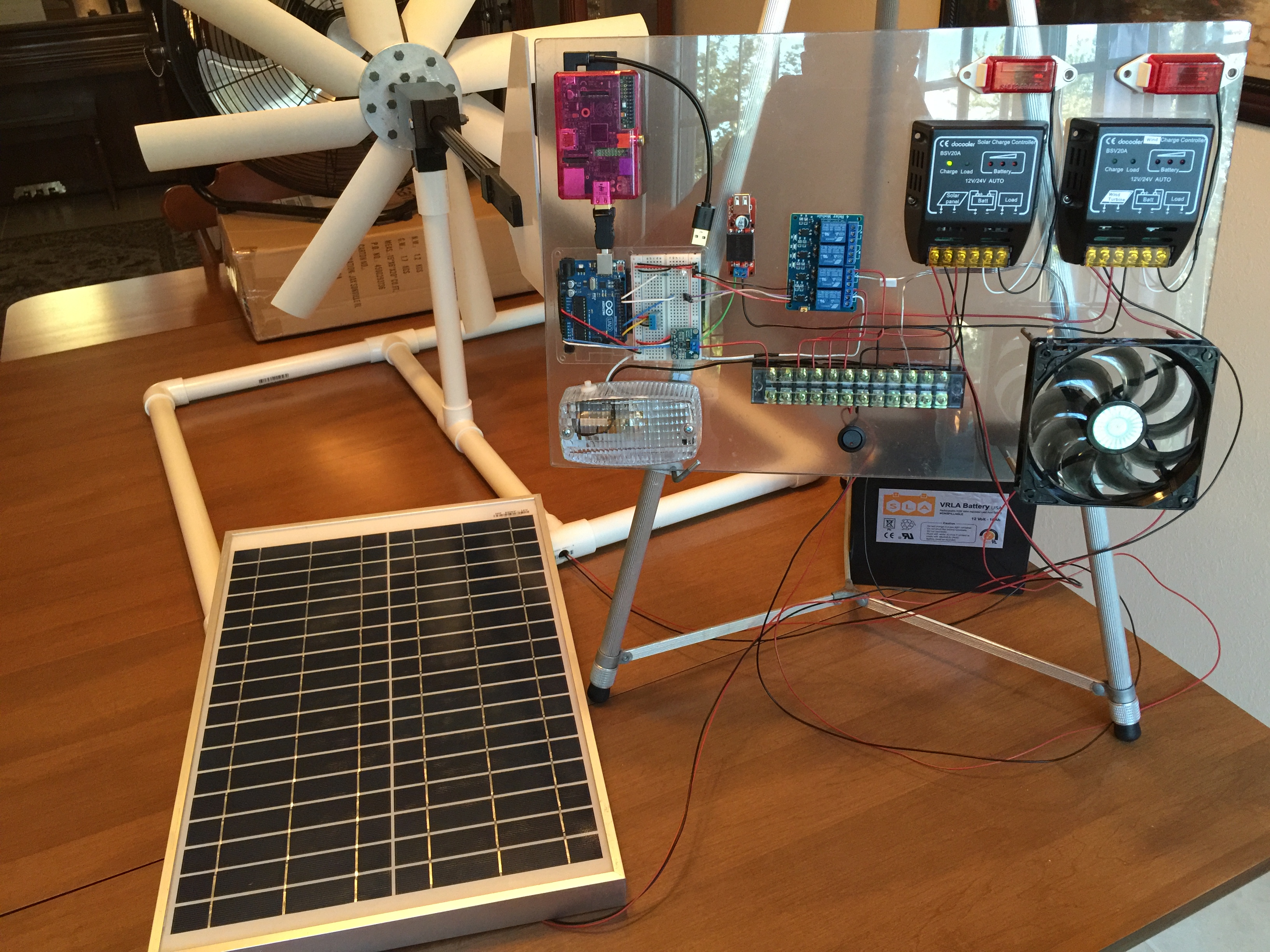
For the portable configuration, here is the hardware I used:
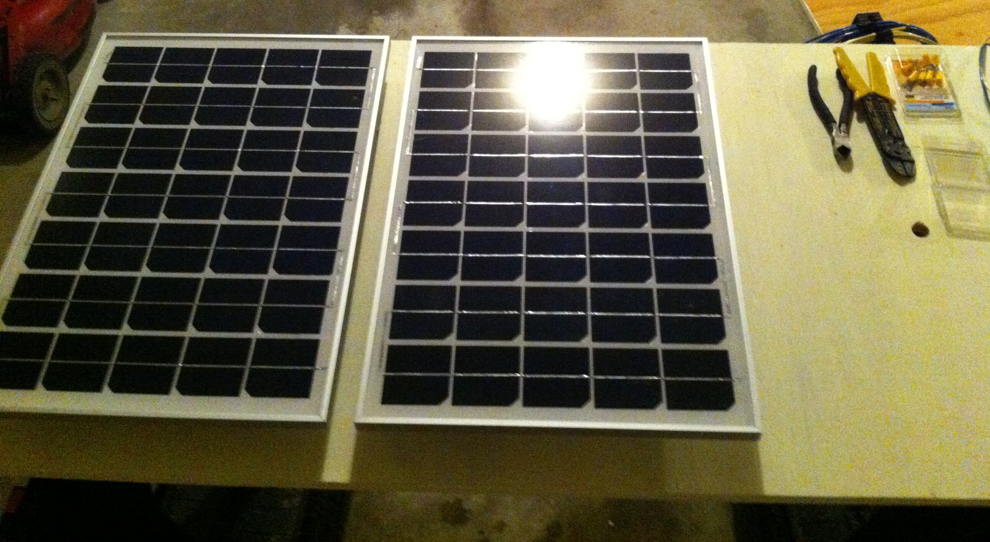
- One (1) 50W, 12V photovoltaic (PV) panel, bought via ebay
- One (1) Cyber 250 wind turbine
- One (1) 18Ah 12V deep cycle battery for energy storage and IoT system power
- One (1) sheet of Lexan cut to size and edged, courtesy of Regal Plastics in St. Louis
- One (1) Raspberry Pi, case, SD card, & wifi plug adapter – this serves as the IoT gateway device
- One (1) 5V DC voltage regulator, allowing me to step down the 12V battery output to the 5V required by the Pi
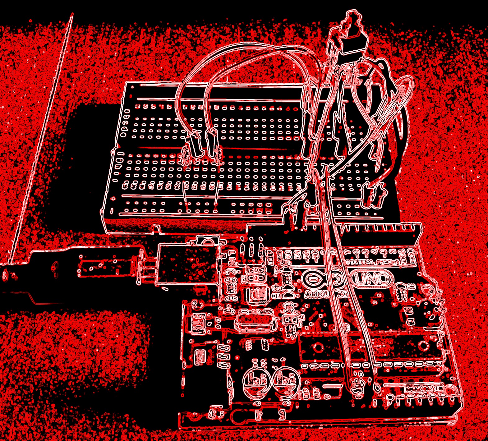
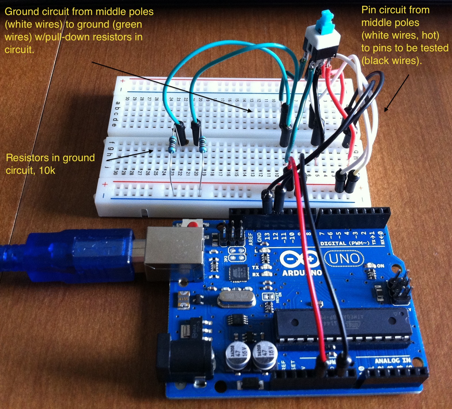
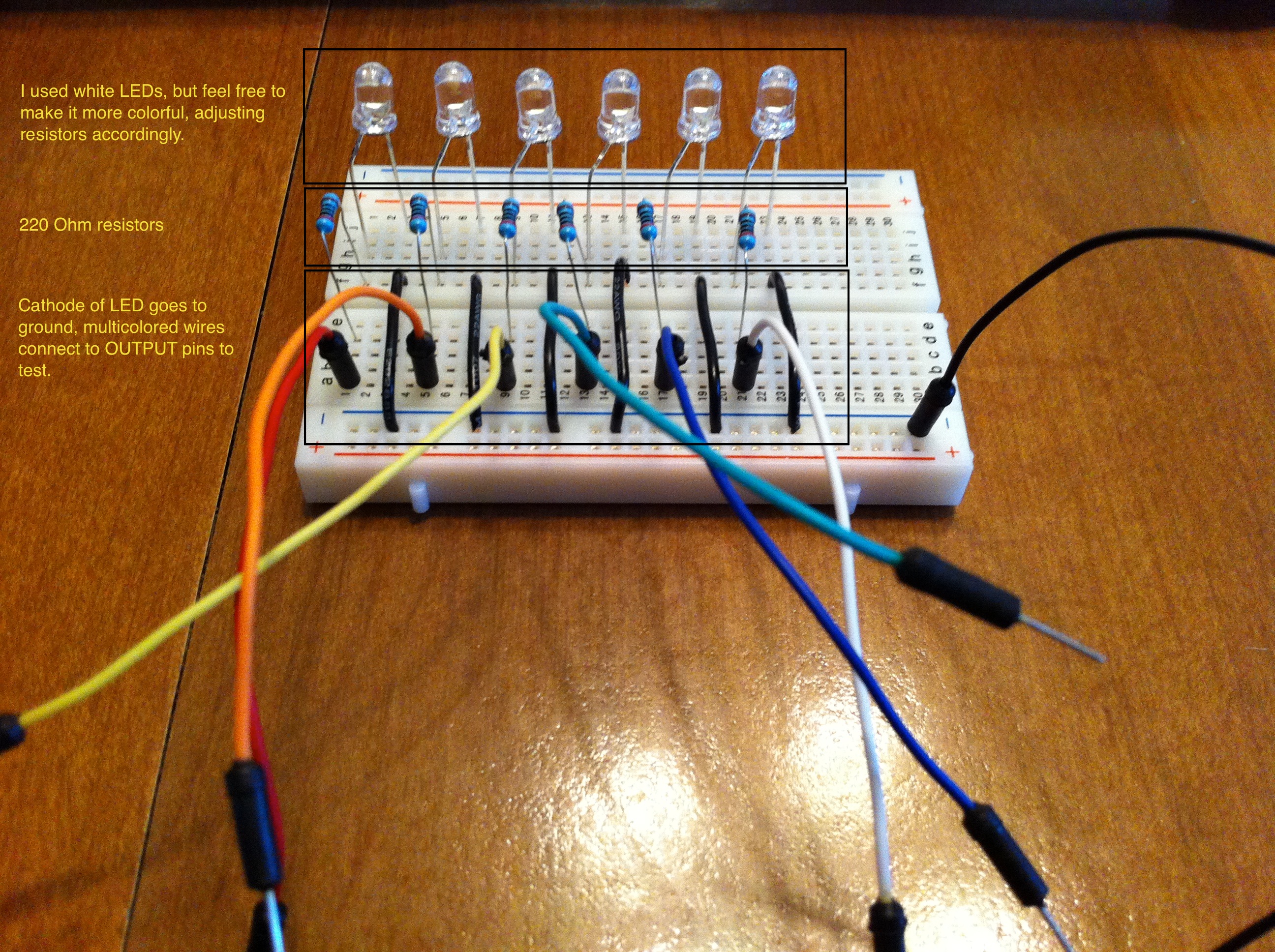
- One (1) Arduino Uno R3, solderless breadboard, combined mounting board – this represents an IoT endpoint
- One (1) Adafruit INA219 high-side DC current sensor breakout
- One (1) Virtuabotix DHT11 temperature & humidity sensor
- One (1) 4 channel DC 5V relay to control physical devices
- One (1) LED case cooling fan
- One (1) interior/dome light to represent building interior lighting
- Two (2) running lights to serve as loads for two RE inputs/charge controllers
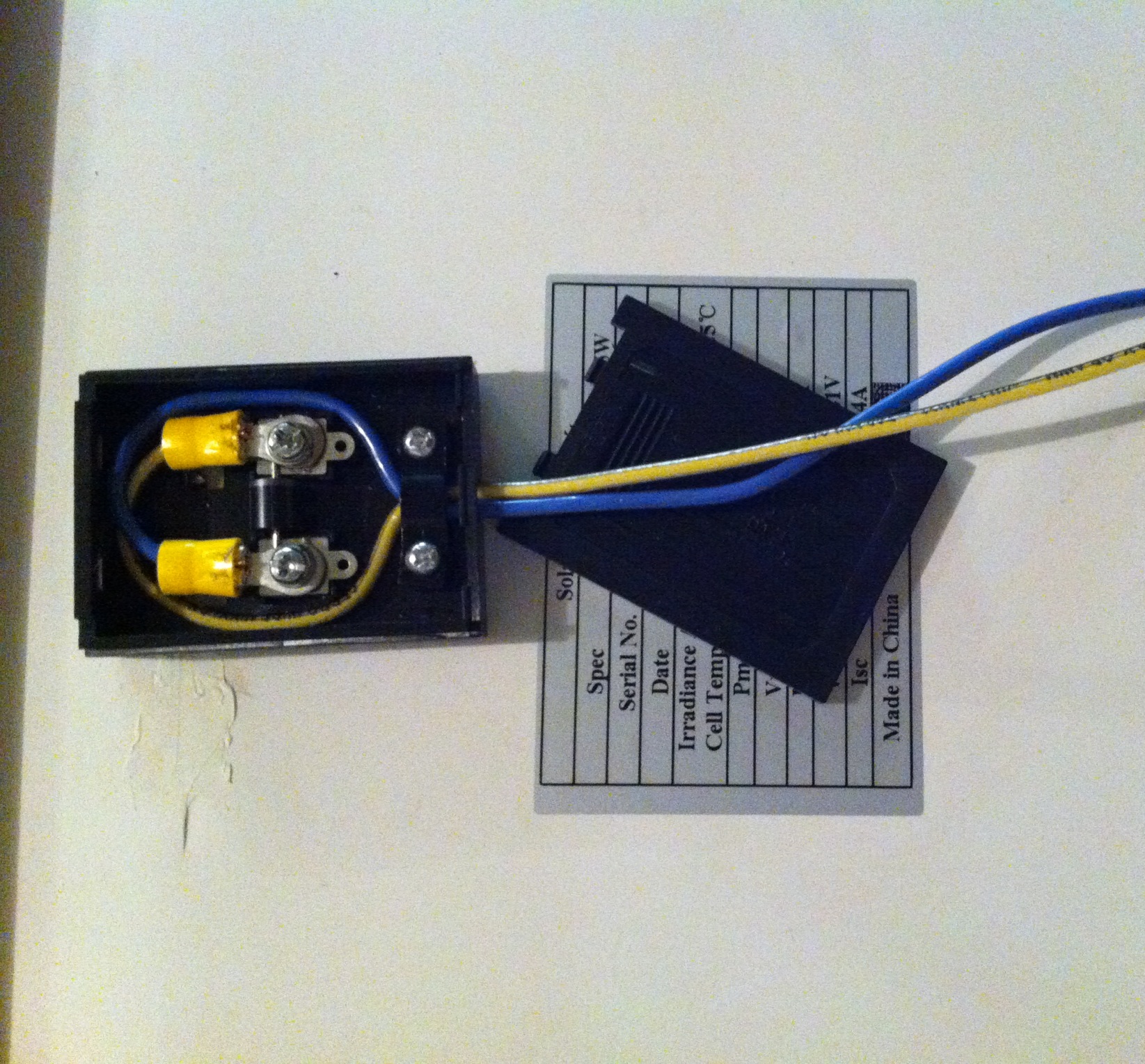
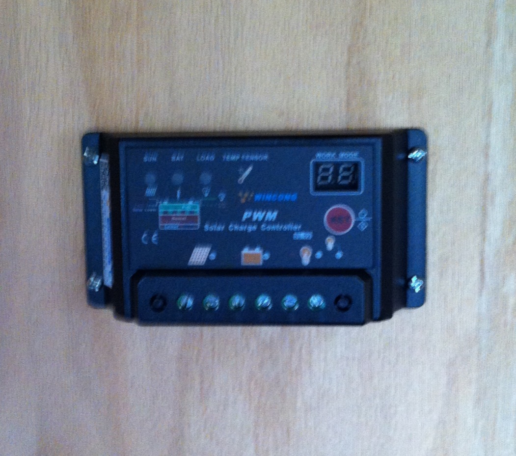
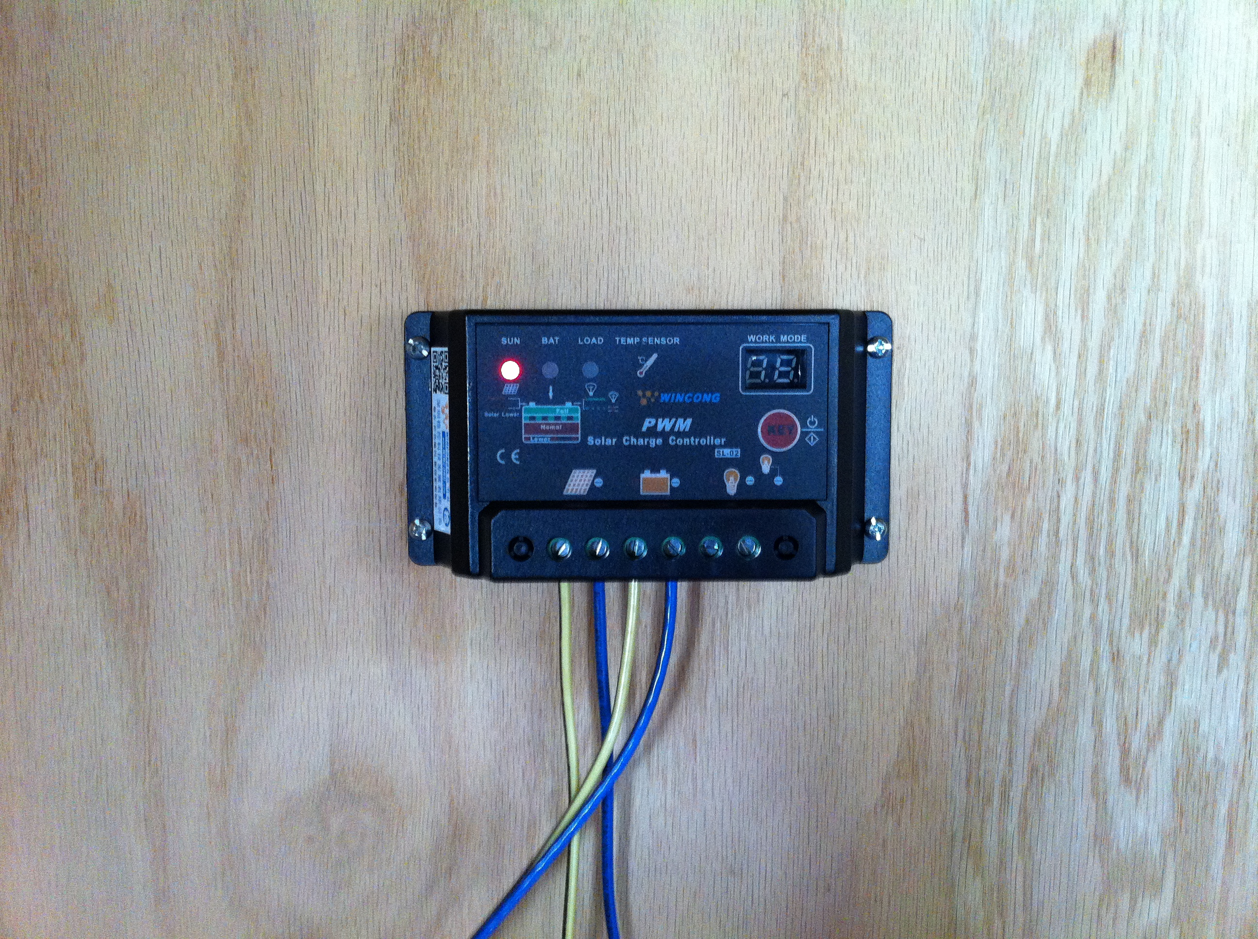
- Two (2) solar charge controllers**
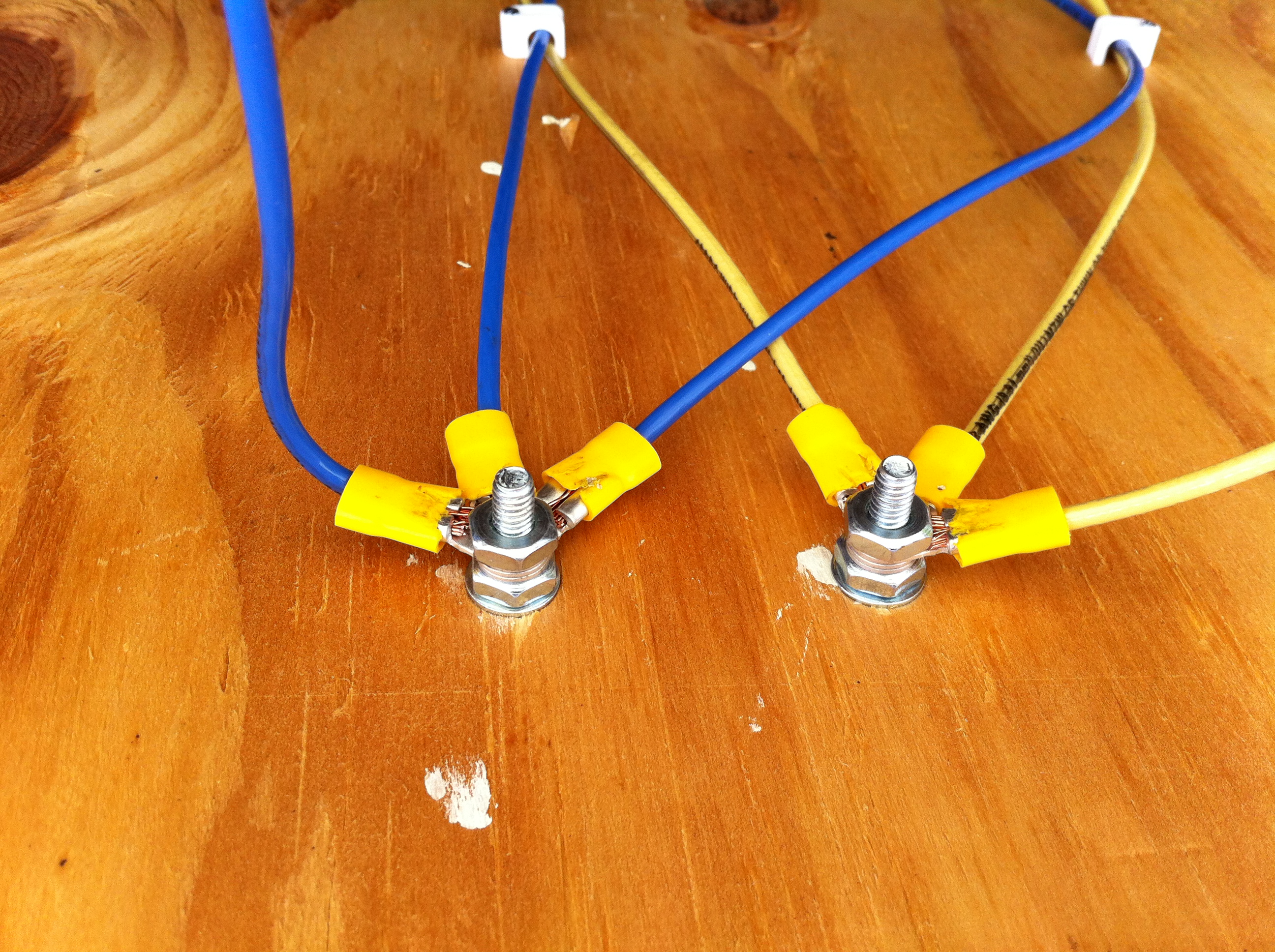
- One (1) 12 position terminal strip/wiring block
- Numerous (?) solder joints, wires, and cables
** I was able to use solar charge controllers for both solar/PV and wind inputs because the wind turbine I selected produces 12V DC power (vs. the AC power output of many turbines) and has a blocking diode to prevent overspeeding, and thus turbine damage. These charge controllers also have load connectors, to which I attached lamps to maintain loads on the inputs, further reducing potential for overspeeding.
This configuration closely follows my permanent installation at my house, albeit at a much smaller scale. For transportability, I’m using only a single 18Ah 12V deep cycle battery instead of several larger-capacity 12V deep cycle batteries wired in parallel to form an energy storage array. And input sensors have been reduced from a full weather station providing temperature, humidity, rainfall, wind speed & direction, ambient lighting, and atmospheric pressure readings to (for the demo system) temperature and humidity. Power readings are comparable for both systems, although I’m using a separate INA219 sensor on the demo system vs. integrated power sensors in the permanent system’s weather circuitry. And my portable system has no actuators to open windows in my power-generation building like my permanent system does. Since the demo system is fully visible to viewers, there was no need to configure a camera for visual observation/checks as I did at home. In actuality, there are few substantive differences between my 24/7/365 production system and this portable demo. 🙂
One nice feature of this portable rig: as configured, it produces far more energy than it consumes, even with a fan providing the “wind” and venue lighting providing the “sun”. Power won’t be a problem.
Software and Related Observations
The software stack for the demo system is nearly identical to that of the production system, with minor changes being made to accommodate the minor differences in attached sensors and physical devices.
I developed software for the Arduino microcontroller to run in Autonomous Mode using sensible defaults, turning on heat when ambient temperature inside the power-generation building is too low, turning on a cooling fan when it’s too hot, and opening windows on opposite sides of the building when temps climb and no rain is present (no windows in the demo config, of course). The Arduino represents an IoT endpoint that regularly (1x/second) polls attached sensors, assembles their readings, and sends them “upstream” to the IoT gateway. It also processes any inputs received from the gateway and acts accordingly; if it receives a command to switch to Manual Override, the software then accepts and processes any subsequent (validated) commands from the gateway until directed to resume with Autonomous Mode.
For the IoT gateway, I used Linux and Java SE Embedded to create a secure and standards-based stack. Raspbian Linux allows me to use utilities like ssh and vnc and to set up startup scripts for the demo config…and since it ships with Java SE Embedded, I have easy access to developer tool support and libraries for everything from RESTful web services to Websocket, which I use for system/cloud communication. I used the JSSC (Java Simple Serial Connector) library to create a wired connection from gateway to endpoint, Pi to Arduino, establishing a reliable comm link within the remote IoT system.
IoT systems are great! But without a way to communicate with, control, and harvest meaningful data from those systems, their usefulness is severely constrained. To unleash the full value of an IoT system, you need the cloud. I used Java SE, Spring Boot, and Spring Cloud OSS to do the heavy lifting with an HTML5/JS user interface, all running on Pivotal Cloud Foundry. I’m still tweaking and expanding it (in my copious spare time 😉 ), but it’s effectively feature-complete…and with only minor differences (to accommodate the sensor/device differences) between the permanent and demo systems.
And…action!
More to Come
Come see me at JavaOne! This will be up and running in the MakerZone all week, so stop by to see it and chat with the crew there. If you have any questions, comments, or feedback of any kind, please ping me on Twitter at @MkHeck or leave a comment below. Hope to see you there!
Keep coding,
Mark

Related Posts:
Tags: Arduino, Cloud, Cloud Foundry, Internet of Things, IoT, java, Raspberry Pi, RE, renewable energy, self powered, Spring