The full details behind the idea and planned execution can be found here (HackFest – Thanks For Sharing!), but to quote one of my favorite movies of all time, “Let me sum up”: this is an unofficial, un-sponsored-by-anyone virtual gathering of friends and soon-to-be-friends just pounding away on their Java code. JavaFX? Sure! Java SE or ME Embedded? Check. Another JVM language? Bring it! Join into a planned project (Hendrik Ebbers is cooking up something special for any who’d like to contribute to it) or BYOP – Bring Your Own Project. Whether you’re diving to new depths in a familiar area or tinkering with a new idea or API, it’s all fair game.
I plan to set up a Google Hangout and keep it open for the duration. Join in for as long (or as little) as you like! Here are the details:
Begins: 1200 (noon) UTC/GMT on Saturday, November 16th Ends: 1200 (noon) UTC/GMT on Sunday, November 17th Where: Google Hangouts
Calendar reminder and invite will be sent to all who want to join in the fun.
Please spread the word (it’s easy, just use the Share/Save button below), and let me know if you can attend, whether for a half hour or all 24! Just email me here to “sign up” and be kept in the loop of any updates, new news, or post-HackFest (subsequent HackFest(s)?) announcements. Looking forward to hearing from you (yes, YOU!) and hanging out, learning, growing, & sharing.
I’ve been testing various “embedded platforms” lately to provide infrastructure for my IoT configurations. In doing so, I’ve installed and configured the GlassFish 4 Web Profile to run successfully on the Raspberry Pi Model B (512M). This post is not meant to be exhaustive or even necessarily prescriptive, but rather an iterative log of what I’ve done and do to configure a Raspberry Pi to “run with the big dogs”, i.e. Java Enterprise Edition (EE) 7.
Please check back (or subscribe to my RSS feed for IoT) to monitor updates. The Internet of Things (IoT) is a very dynamic space and will likely remain so for some time! The only constant…is change. 😀
Document version 1.3 (This number will change as I make updates and is for reference only)
Steps to Install/Configure GlassFish 4 on the Raspberry Pi
Download the latest version of Raspbian Wheezy from here. You can install NOOBS, Arch, or some other distro, but I chose Raspbian. Note that this distro includes the Java SE 7 JDK, which simplifies things a bit. If you wish to use an previous Raspbian build that doesn’t already include the JDK, simply run “sudo apt-get update && sudo apt-get install oracle-java7-jdk” from your Pi shell.
Make a bootable SD card by doing the following (on my Mac; Windows steps will vary a bit):
Unzip/decompress the downloaded image from step 1
Open a Mac terminal window
Run “diskutil list” to see drives
Plug SD card into SD card slot
Again run “diskutil list” to see drives, now including the SD card
Run “sudo diskutil unmountDisk /dev/diskn“, where n is the disk number of the SD card (as reported by diskutil)
Issue the following command, being very careful to ensure the of= parameter points to the SD card! If not, you can overwrite something you’d rather not…like your boot drive: “sudo dd if=<path/name_of_Raspbian_image.img> of=/dev/diskn bs=1m”
Once dd completes, issue “diskutil eject /dev/diskn” to eject the SD card
Plug the SD card into the Pi, plug ethernet cable and power into the Pi to boot.
At this point, you’ll need to determine current (dynamic) IP address of the Pi. I plugged in my Atrix Lapdock and did this “on the Pi”, but you can also use nmap or connect it to HDMI (TV) and USB keyboard.
Run “sudo raspi-config” and set the following:
Expand the file system to take the entire SD card (not just what the image initially does)
Under Internationalisation Options, change Locale, Timezone, & Keyboard layout as desired
Overclock to High (950MHz). I’ve tried Turbo, but it seems prone to flakiness & data loss…at least for me.
Under Advanced Options, change Hostname to desired Pi name, Memory Split to 16 (as a server, we can skinny the GPU memory allocation to maximize “main” memory), and enable SSH. You can also “Update this tool” (raspi-config) to the latest version, never a bad thing.
Select “Finish” to reboot the Pi & use the new settings
Ensure the Pi has a static IP by doing the following (recommended for any server):
Run “ifconfig -a” and “netstat -nr” on the Pi to gather the following information: current IP (if you want to keep it), netmask, gateway, destination, and broadcast. Jot these down.
Make a backup of /etc/network/interfaces by running “sudo cp /etc/network/interfaces /etc/network/interfaces.orig
Modify the interfaces file. I used vi, but use whatever editor you can & are comfortable with! The vi syntax is “sudo vi /etc/network/interfaces”
Change the line that reads “iface eth0 inet dhcp” to “iface eth0 inet static” and add the following lines:
address 192.168.1.nnn (this is the IP address you want the Pi to have & keep)
netmask 255.255.255.0 (or whatever was shown in ifconfig -a above)
network 192.168.1.0 (or whatever was in the destination column, 2nd line from netstat -nr above)
broadcast 192.168.1.255 (as shown in ifconfig -a)
gateway 192.168.1.1 (or what was shown in either ifconfig or netstat)
Save the file
Reboot the Pi (“sudo reboot”)
NOTE: You’ll also need to tell your network DHCP device/router that the IP address you statically assigned to the Pi is off-limits for assigning to another device
Download GlassFish 4 Web Profile (or full EE platform) from here. I chose the Zip installer.
Copy the GlassFish .zip file to the Pi (“scp glassfish-4.0-web.zip pi@raspi:.”). I have an entry in my Mac’s /etc/hosts that points “raspi” to the Pi’s static IP address.
On the Pi, “install” GlassFish by doing the following:
Run “sudo mkdir -p /app/glassfish” to create GlassFish app parent directory
Run “sudo chown pi /app/glassfish” to assign directory ownership to the pi user. Not absolutely necessary, but you typically don’t want root to own everything (although honestly at this stage & for this install, it’s not critical)
“cd /app/glassfish” as the pi user to change directories into the “install” directory
Run “unzip ~/glassfish-4.0-web.zip” to extract the GF files into this directory
Now to configure GF to allow for remote administration/configuration using its web console app:
“cd /app/glassfish/glassfish4/bin”
Run “./asadmin change-admin-password --user admin” to assign a password to the admin user. The admin password defaults to a blank password, a no-no for GF remote admin.
Run “./asadmin start-domain” to start the default domain (which comes preconfigured in GF)
Run “./asadmin enable-secure-admin” to enable remote administration using the web console
In order to take utilize remote admin, stop the domain by running “./asadmin stop-domain”, then…
Start the domain once more with “./asadmin start-domain”
From your workstation/laptop, plug this into a browser address bar: “raspi:4848” (substituting the name of your Pi per your /etc/hosts file) or “192.168.1.n:4848″ (substituting the IP address or your Pi) to load the GF admin console
Login and relish the fact that you now have a full Java EE 7 stack (or web profile) running on your Raspberry Pi server!
I’m capturing this from memory, so it’s possible I’ve missed a step I performed or have related it not-exactly-perfectly…but if you spot something that isn’t quite right or have questions, please let me know! I’ll update this document accordingly. YMMV (Your Mileage May Vary), especially if you’re using a Linux or Windows machine for your workstation, but hopefully, this will get you that much closer to your own tiny Java EE 7 stack for your own growing IoT empire.
All the best,
Mark
P.S. – Follow me on Twitter at @MkHeck for more Java/IoT adventures…yours and mine (and ours)!
Renewable energy (RE) has long been a passion of mine, but practically speaking, it simply hasn’t been cost-effective to implement at a personal level. Factoring in credits, location, type of RE, etc. can often tip the scale, but generally speaking, an investment in RE would require more commitment than simply “running the numbers.” No judgment here, I understand and appreciate both sides of that argument.
In recent years, though, things have changed. Not entirely, and not across the board even now…but with inexpensive (yet quality) RE equipment being produced in the US, China, and many locations throughout Europe, one can begin to experiment with RE on a much smaller scale and determine if/how it makes sense for your particular situation.
As a software engineer, I also work to integrate whatever I build into a more manageable, usable system. Physical computing promises many things, which I’ll coarsely lump into the term “better living” – but to do it right requires more than just assembling some hardware. The intersection of devices with software and the greater internet results in what is often termed the “Internet of Things”, or the IoT…and this is where the potential for “better living” can skyrocket, if things are properly integrated. It’s a small and limited example, but how much more useful is a fully-integrated system that is easily managed from anywhere on the planet than a complex system composed of numerous components…all of which must be monitored individually and manually?
For this post, we’ll focus solely upon one small portion of that integrated system: adding PV, or photovoltaic (solar) panels to a functioning small-scale RE system. Before these additions, the system consisted of:
Wind turbine
Deep-cycle battery bank
Arduino to control sensors, radio transceiver
Temp/humidity and current/voltage sensors
Radio transceiver, primarily for comm link to send readings
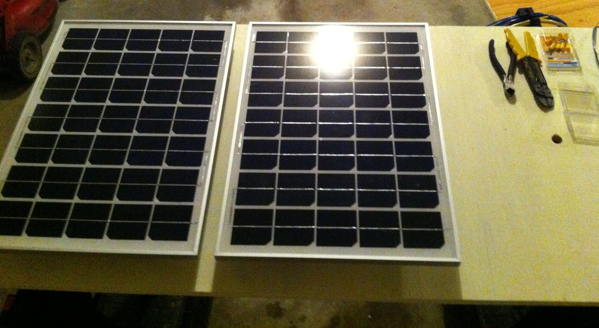
Now we’re adding a solar charge controller and initially, two 25W solar panels wired in parallel for a total of 50W maximum.
In future posts, I hope to elaborate on the software side because (as stated above) that is where the difference truly lies. For now, here are some pictures (and a very short video) of the PV addition:
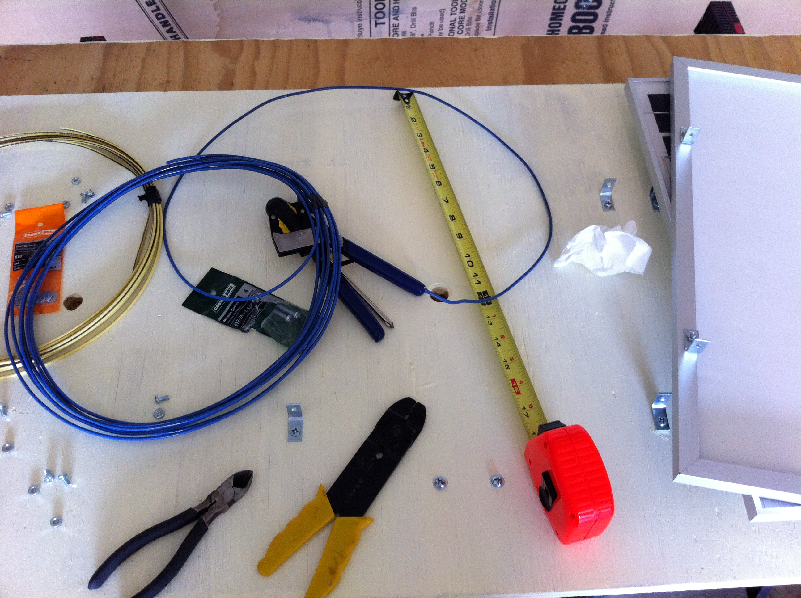
Connecting the PV Panel
Mounting the PV Panels to the Backing Board
Initial Two Panels Mounted
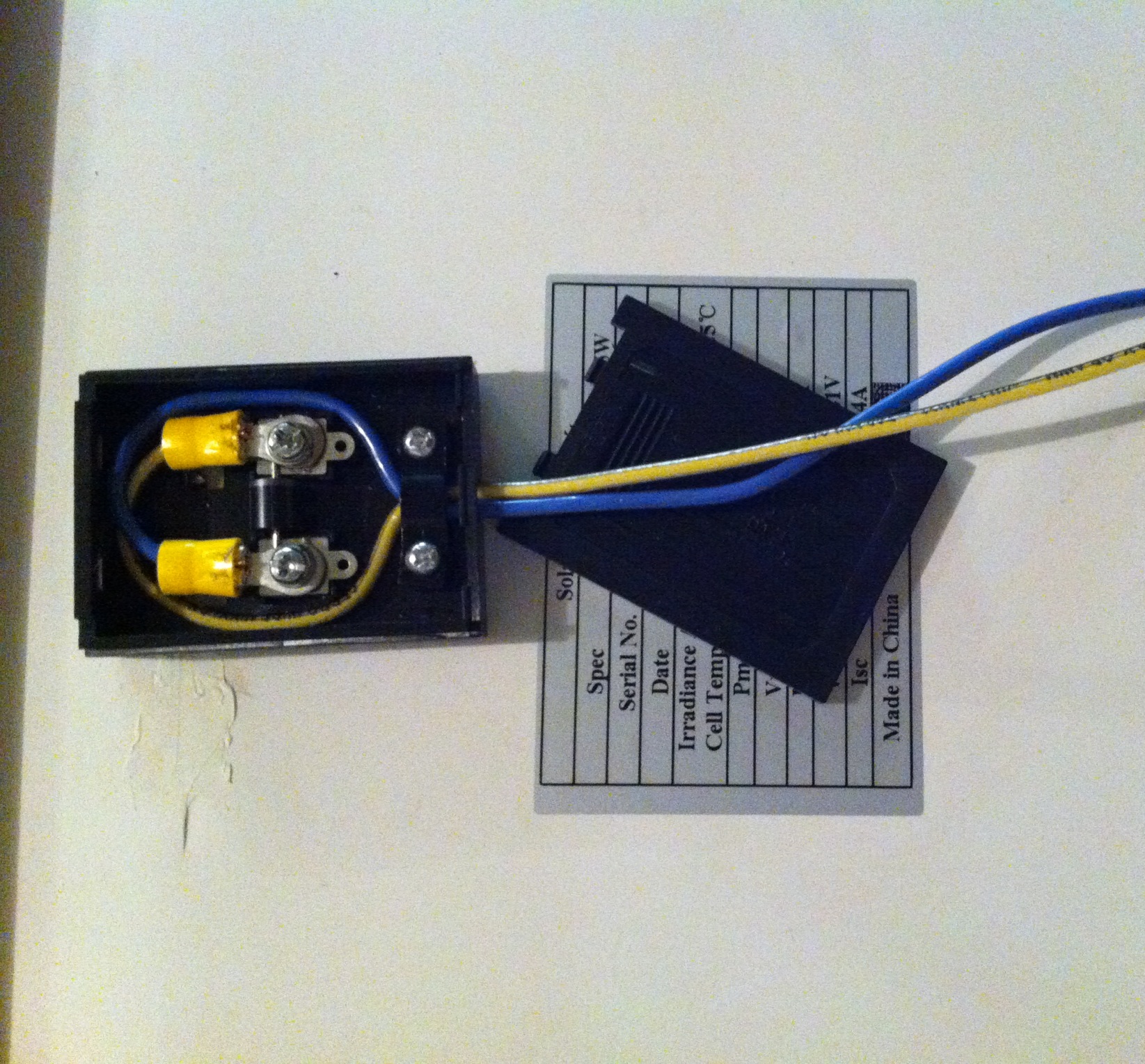
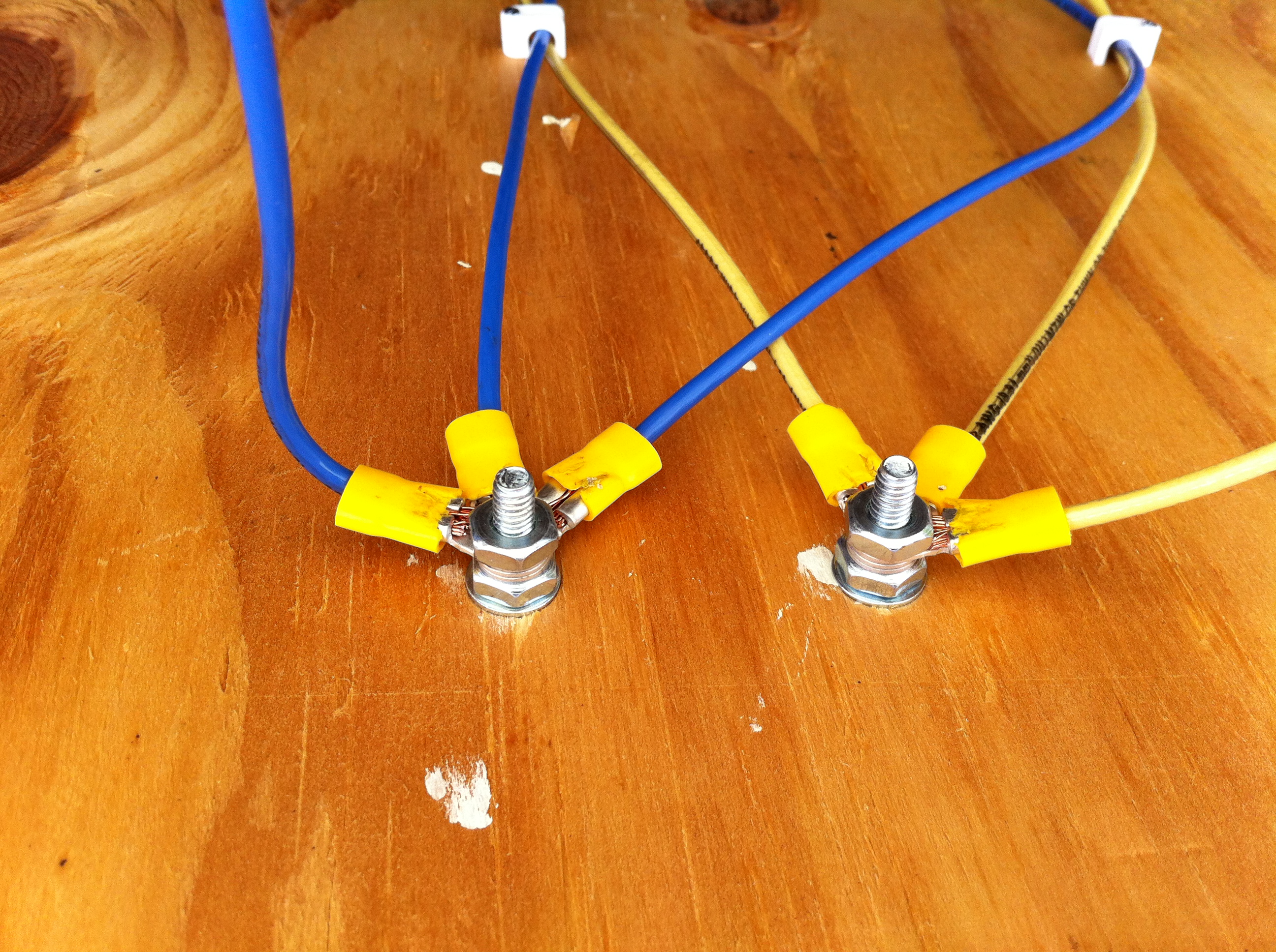
Simple Wire Terminals on PV Board
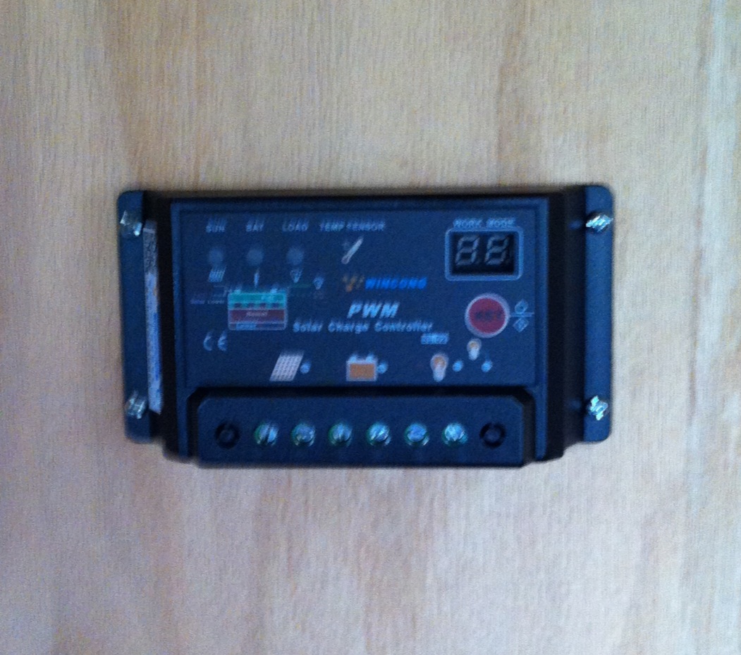
Charge Controller Mounted, Not Yet Connected
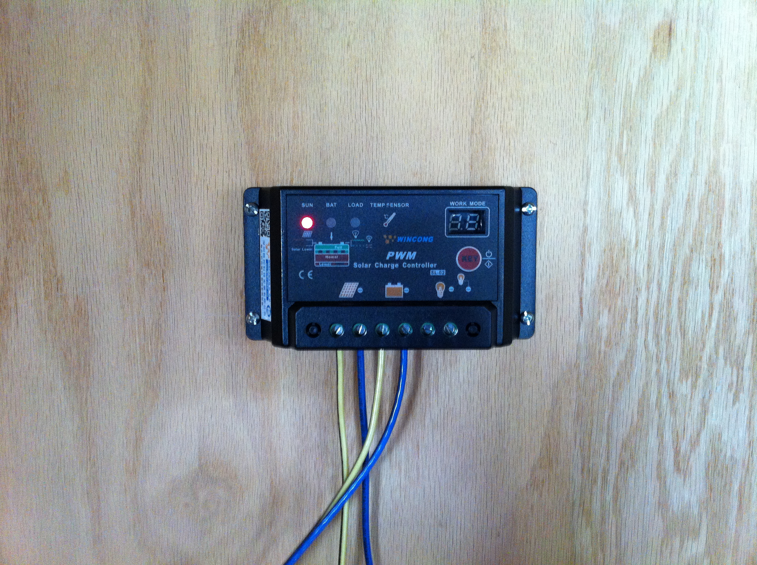
Charge Controller Mounted AND Connected! The “Sun” light indicates power from the panels; the “Battery” light flashes while charging attached batteries.
And finally, a short video to give a glimpse of the PV portion of the system in action:
In future posts, I plan to provide more information about the “good stuff” (teaser: JavaFX, Java Embedded Suite, more Arduino, BeagleBone Black, wireless management, and more!), but a system must exist before it can be monitored and managed. As we continue to “build out” the system, those opportunities will only increase. Stay tuned, and please feel free to comment below or drop me a line. Thanks for visiting!
If you’ve worked (or played) much with Arduinos, you’ve probably run into “dead pins” – or wondered if you had. How can you tell which pins, if any, are unusable on an otherwise perfectly good board?
There are probably more precise ways of determining what is wrong, and perhaps even ways to repair some defects…but for those of us embedded folk who work far more with software than hardware, this is a quick way to confirm which pins don’t work properly with sufficient precision so you can label the board and move on. To quote Steve Jobs, “Real artists ship.” 🙂
To test digital pins, you need to test both pinModes: INPUT and OUTPUT. (There is also INPUT_PULLUP, but that is only relevant if using the internal resistors vs. external ones.) I created two sketches, one to test pins with a call to digitalWrite() to light up connected LEDs, and one to read a switch using digitalRead(). Those are the software components necessary, and they’re available at my ArduinoPinTests GitHub repository.
The hardware portion of the test can be easily assembled as well. Here are the items I used; feel free to substitute similar components as desired:
Solderless breadboards (2, one for each: input & output)
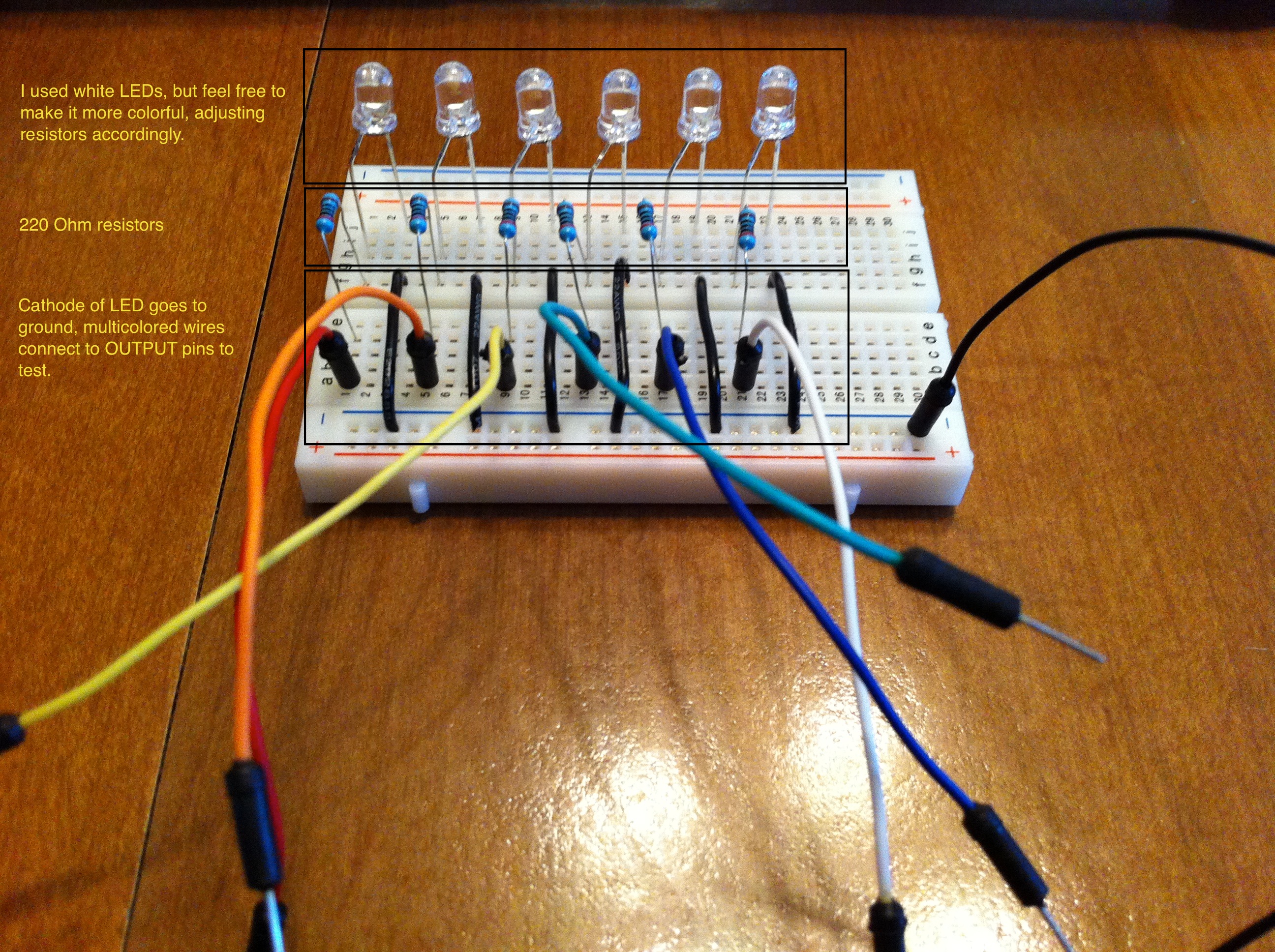
LEDs (6)
Resistors, 220 Ohm (6) (for output test board)
Resistors, 10k Ohm (2) (for input test board)
microtivity IM211 push-and-lock switch (for input test board)
Necessary wires to put it all together
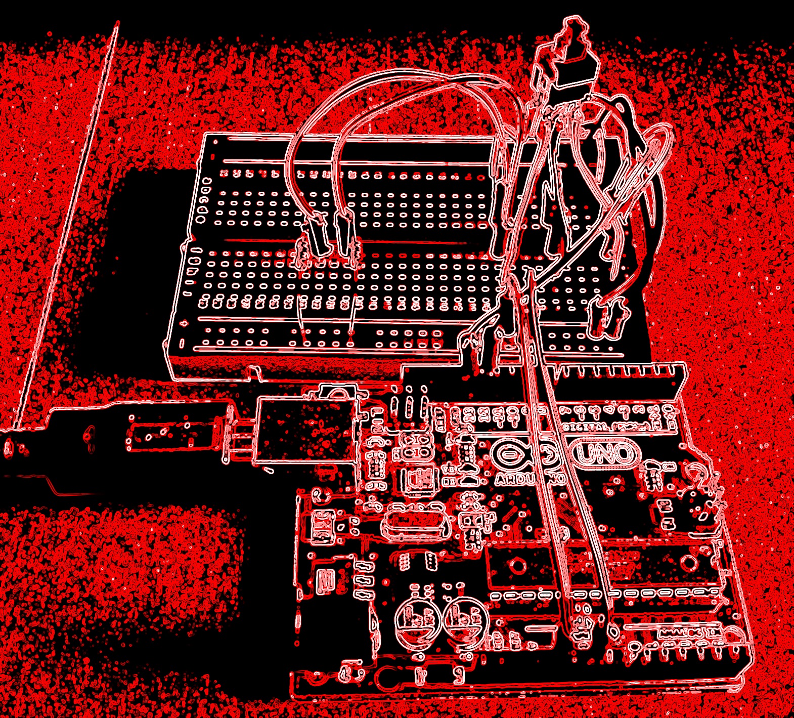
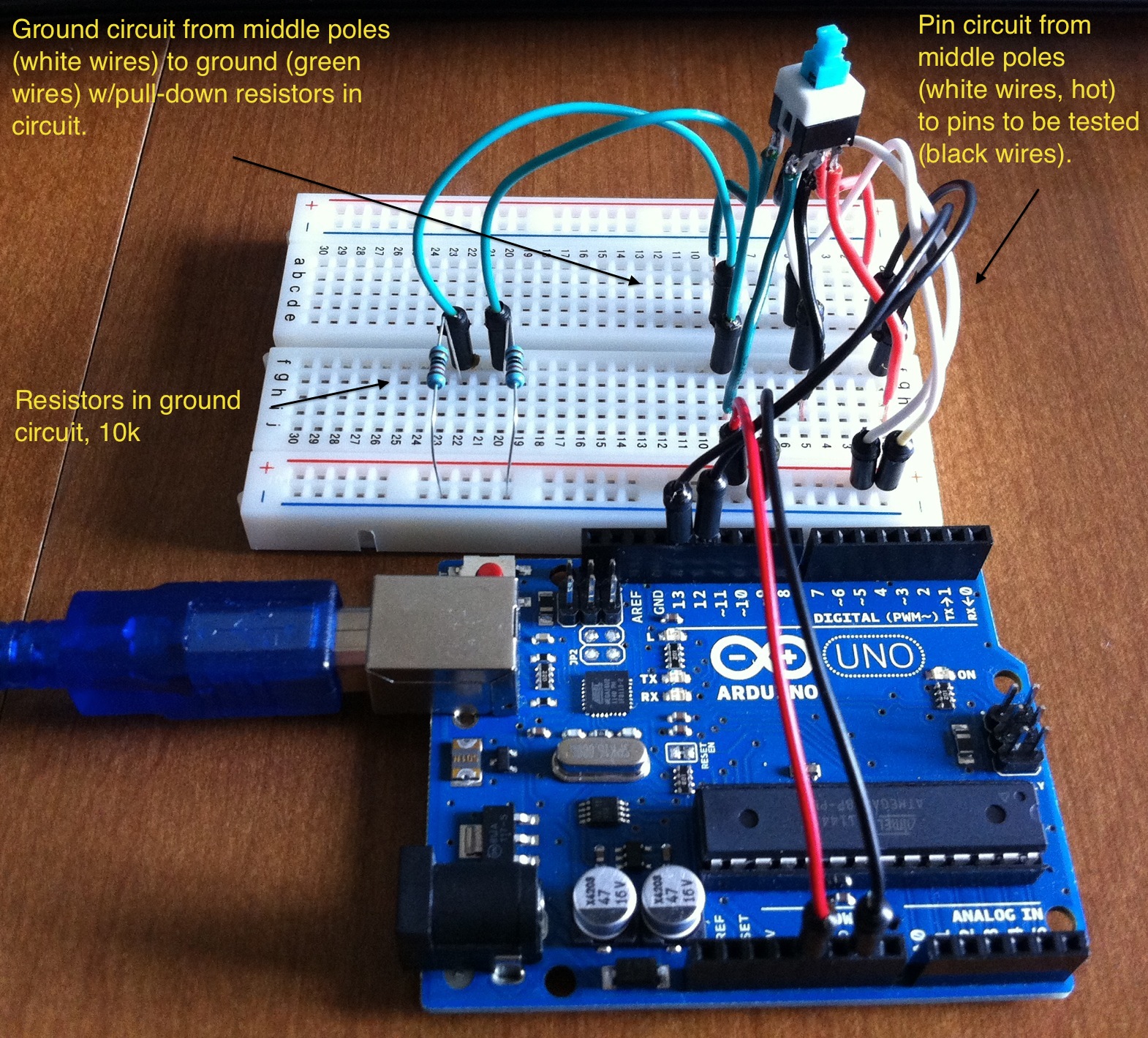
It has been said that a picture is worth a thousand words. Here are two thousand for you!
Digital Pins (In) Test Board
Digital Pins (Out) Test Board
The Bottom Line
If you have pins you think may be dead on your Arduino or clone board, grab some spare parts, visit my GitHub repo, and within minutes you can find out if/which pins are out of commission and get back to configuring devices and pounding out code. Now…back to business!